Porcelain Insulator News
by Elton Gish, NIA #41
Reprinted from "Crown Jewels of the Wire", February 1989, page 24
This month we will feature a multipart porcelain insulator that was recently
found by Mike Spadafora on a trip he made last summer to Ontario. More
specifically, on an old power line between Niagara Falls and Toronto.
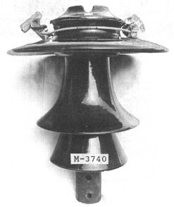
Mike found two identical three-piece, multipart insulators which style is
shown in my new book, Multipart Porcelain Insulators, as M-3740. The insulators
were cemented on steel pins and bolted to old 50' tall steel towers. Removing
these jewels proved difficult as they weighed nearly 30 lbs and had to be
lowered to the ground with a rope. The original bronze cable clamps were still
attached to the crown. As you can see from the photo below, M-3740 is one of the
early lily-shelled styles.
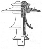
The lily-shell design was patented by C. C. Chesney on June 7, 1904. The
drawing used in the patent (below) is identical to the M-3740. This design
called for each adjacent skirt to be concave-shaped and smaller in diameter so
water, dripping from the above skirt, would fall clear of the skirt below.
Insulators made with the lily-shell design are quite attractive and very
sought after by porcelain collectors. They were neither very practical nor long
lived in actual operation and few specimens of the lily-shell styles have
survived, particularly the larger ones.
Each skirt section was very long and necessitated having a long cement joint.
These long cement joints proved a disaster. The cement expanded due to the heat
generated from internal electrical stresses, causing the insulator shells to
break and shatter the insulator. Indeed, Mike reported that almost all of the
insulators he saw along the line were broken, apparently from cement expansion.
The lily-shell styles posed still another problem, that of failure due to
electrical puncture. Electrical stress was generated by the tall design
producing an imbalance in the electrical field around the insulator (the heat
generated from this stress effectuated the cement expansion problem). Since the
porcelain body offered less resistance than the air surrounding the insulator,
the electrical current found an easier path to ground by simply forcing its way
through the porcelain shells to the top of the pin (causing a tiny hole through
the porcelain shells) rather than arcing over the outside of the insulator to
the pin. The resultant minute puncture hole rendered the insulator ineffective
at the operating voltage. Insulators had to be individually removed and tested
to locate which ones were defective.
As a result of the cement expansion and puncturing problems, most of the
large lily-shelled styles were discontinued in the early 1910's in favor of
styles where the height of the insulator was less than the diameter of the top
skirt. This allowed for flashover before the insulator could be damaged by
electrical puncture, and helped to reduce the electrical stress, the resultant
generation of heat, and the cement expansion problem. The design causing the
greatest puncturing problems was M-3890 which was 4-1/2 inches taller (19")
than the diameter (14.5") of the top skirt. Also, new designs required less
volume of cement to reduce the expansion problem. Many patents were granted from
1915 to 1925 for various cementing techniques, and soon the cement problem was
understood and eliminated. Multipart designs that were developed in the early
1920's are practically indistinguishable from modern designs.
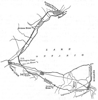
Now back to the M-3740. Mike found this insulator on the 60,000 volt, 75 mile
line that was installed in 1905 by the Toronto & Niagara Power Company. The
insulators were made by the R. Thomas & Sons Co. in 1905 and the line began
transmitting power in late 1905. The dimensions of M-3740 are: 14 - 9 - 7 x 14
(where the first three numbers are the skirt diameters and the last number is
the height in inches). The following map from the "Electrical World &
Engineer" ("E W & E") dated September 16, 1905 shows the route of
the power line.
The "E W & E" dated July 8, 1905 describes the bronze cable
clamp:
"Instead of a tie wire, a novel combination of clamps is employed to
secure the copper cable on each insulator This clamp is made up of two separate
clamps that grasp the cable at opposite sides of each insulator, and of two half
circles of hard-drawn copper wire of 0.187 in. diameter. Each half circle of
this wire joins one-half of each of the opposite clamps, and fits about the neck
of the insulator just below its head. Two bronze castings, one of which has a bolt extension that passes through the other, and a nut, make up
each separate clamp. When the combined clamp is to be applied, each side is
separated by removing the nut that holds them together, the half circles are
brought around the neck of the insulator and each of the side clamps is then
tightened on to the cable by turning the nut that draws its halves together.
This complete clamp can be applied as quickly as a tie wire, is very strong and
does not cut into the cable."
An interesting note was found in the "E W & E" dated March 29,
1902 announcing the proposal for the line to bring "Niagara power in
Toronto". Opposition to the line feared that Toronto would derive so
much advantage from cheap electricity as to be in a position to draw industries
from other communities and make the rest of the Province [Ontario] a
desert."
The two photos below are from the September 16, 1905 issue of "E W &
E" and shows two of the 50' steel towers used on the line. Most of the
towers had only six insulators. The towers in the two photos were used at
locations encountering greater mechanical stresses and used either 12 or 18
insulators.
The next photo (below) was found on page 323 of the book Electrical
Transmission of Water Power by Alton D. Adams published in 1906. The book
contains a rather complete description of the Niagara-Toronto power line and it
is a compilation of the series of three articles that appeared in the 1905
issues of "E W & E".
While it is amazing to find one of these early large lily-shell insulators
still on the original pole, it is rewarding to be able to locate such a wealth
of information which describes in detail the insulator and the power line on
which it was used. Now if we could just locate a few of the other early, large
classic lily-shell insulators such as M-3250, M-3890, M-3990, M-4380 and
M-4390. Probably most of these beauties have been lying in an old dump for the
past 75 years. But, then again, you might find one still on the original line in
a remote area and long since abandoned.
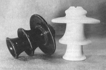
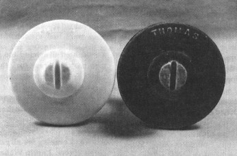
The last two photos (shown following) are of two salesmen's samples
that I recently acquired. We show these in this article because they are exact
replicas of the M-3740. They were evidently made circa 1905 - 1910.
Each were made from three pieces of dry process porcelain, glazewelded
together, with the embossed name "THOMAS" along the outer, top edge of
the top skirt. The dimensions (in inches) of these miniatures are: 2-1/4 -- 1-1/2
-- 1-1/8 x 2-1/2 tall. They are both quite rare. While several of the brown ones
are known, only two white Thomas miniatures have ever been reported.
| 
)
)
)
)
)
)
)
)
)
)